![]()
- Details
- Published: 09 January 2013
Geometrical acoustics [1] is a geometry based room acoustics modeling method, in which sound is supposed to propagate as rays. In other words, the wave nature of sound propagation is neglected. However, with sufficiently large number of rays the prediction results are reasonable, in particular at high frequencies when the wave length compared to dimensions of the surfaces is small.
Ray Tracing
One of the most widely used modeling technique is ray tracing [1]. A large number of rays are emitted from the sound source. When a ray hits a surface of the room, it is reflected and the ray continues in an other direction. Usually the ray is reflected in the specular reflection direction, which means that the angles between incoming and outgoing rays with respect to the surface normal are equal. Each ray is supposed to carry a small portion of the sound energy emitted by the source. Some of that energy is absorbed by the surface at reflections. The portion of the energy absorbed is determined by material- and frequency-dependent absorption coefficients. Some of the rays eventually hit the receiver, which is modelled as a finite-size volume, such as a sphere. Those rays contrubute to an echogram, which collects the arriving energy in a time-dependent response. The arrival times are calculated by dividing the ray path length from the source to the receiver by the speed of sound.
The ray tracing technique can be extended to model non-specular reflections by generating the outgoing rays at reflections randomly from an angle distribution, instead of using only the specular direction. In this case, the energy is divided between the specular ray and other rays according to a scattering coefficient.
Ray tracing can be seen as a stochastic method, where the space of possible reflection paths is sampled with rays. This also means that some paths might be missed due to low sampling density or their contribution to the echogram can be miscalculated. Increasing the number of rays or splitting them later during the tracing usually improves the quality of the results.
Image Source Method
Another common modeling technique is the image source method [2], [3]. Image sources are created by taking a mirror image of the sound source around the planes at which the surfaces of the room lie. Each mirror image is treated as a source which emits sound like the original source. From the receivers point of view, the sound emitted by these image sources corresponds to the first order reflections from the surfaces which were used in creating those image sources. The ray path can be reconstructed by starting a ray from the receiver point towards an image source, and when the reflecting surface is hit, then continuing the ray towards the original source. Higher order reflections can be modelled by creating image sources of the image sources recursively, and tracing the paths backwards from the receiver in a hierarchy of image sources.
The validity of the reflection paths created as above must be checked before constructing an impulse response out of them. There are two ways a path may by invalid: the ray does not hit the reflecting surface corresponding to an image source or the ray hits another surface before hitting the reflecting surface. It is possible to use ray tracing to test this, and discard false paths.
After the validity of the paths is confirmed, they can be added to the room impulse response. The path length is related to the arrival time as in ray tracing. The amplitude of the peaks corresponding to the reflections is inversely proportional to the path length. Unlike in ray tracing., it is also possible to account for the phase information, since the specular reflection paths are accurately modelled.
One limitation to the image source method is that the number of image sources grows exponentially in relation to the order of reflections. Thus, it is only feasable for low order reflections.
Beam Tracing
The image source method can be accelerated by taking into account the validity of the paths already during the creation of image sources. This can be done with a technique called beam tracing [4]. Instead of starting rays from the sound source, cones or beams are sent forward from it. In an ideal case, the full solid angle around the source is divided between the beams so that none of them overlap or leave gaps between them. A convenient way of doing this is using the source as the apex and the polygons visible to it as bases of the cones. Then the beams are traced further and flipped at the surfaces so that each beam edge is reflected like specular rays in ray tracing. Incidentaly, the apex of the cone is then the image source corresponding to the surface at which the beam is flipped. When a beam hits multiple surfaces, it is split so that the parts of the beam covering different surfaces are put into different beams. Those beams are further flipped and traced. The beams are stored in a hierachical structure called beam tree. At the first level of the beam tree are the initial beams. When the beams are flipped and split, new levels are constructed in the tree under the previous level of beam. This structure remains unchanged for a fixed sound source position, and it can be precalculated and stored.
To find the reflection paths, the first step is to examine in which beams the receiver position lies. When those beams are found, the paths can be generated as in the image source method by tracing backwards from the receiver through the image sources and eventually to the source. The image sources are either explicitly stored in the beam tree or they are quickly calculated from the list of surfaces that are hit during the tracing of a given beam. Although the handling of beams requires extra effort compared to the image source method, the beam tree is much narrower than the hierarchy of image sources of the same maximum reflection order. In addition, if the beam splitting is done accurately, there is no need for validity checks.
The beam tracing technique usually allows higher order of reflections to be modelled with the same computation time when compared to the image source method. The benefit is greatest in densely occluded environments such as office spaces with narrow corridors. In large open spaces, like in the concert halls, large part of the image sources are valid, and thus the performance gain of beam tracing is less significant. On the other hand, beam tracing is efficient in interactive applications, where the sound source is fixed, but the receiver is moving, because the reflection paths can be easily updated by utilizing the precomputed beam tree [5].
Radiance Exchange Methods
While specular reflections are physically correct representations of reflections from rigid flat surfaces with infinite extent, in practice some surfaces produce more diffuse-like reflections. Diffusors in concert halls are an example of such surfaces. They can be modelled either with a modified ray tracing algorithm as mentioned earlier, or with an algorithm specialized in diffuse reflection modeling. They can be used in combination with the other algorithms or as such for room acoustics modeling [6], [7].
The fundamental idea behind this class of modeling algorithms is that the surface of the room is divided into small elements and acoustic radiance exchange between them is modelled. Initially, the sound source radiates onto the surface elements. Then each of these elements reflects the incoming radiance in all directions according to the diffuse reflection model. This radiance arrives at other elements and is reflected further. The radiance exchange between the elements can be explicitly calculated by utilizing their geometric properties [7]. Part of the radiant energy is absorbed at each reflection and the total energy in the system decays as the radiance is iteratively propagated between the elements. When the total energy is below a threshold, the propagation can be terminated. In the end, each element has stored an echogram based on the radiant energy that it has received over time. Then, a final gathering step is performed, where the stored echograms contribute to the echogram at the receiver position according to their geometric relationships.
The results of the radiance exchance methods resembles that of ray tracing, because the final result is an echogram. On the other hand, because the number of elements is fixed in the beginning, these methods do not suffer from the exponential explosion in the number of image sources. Thus, they are well fit for modeling the late reverberation. The main limitation is the reflection model, which is either ideal diffuse or directional diffuse [7]. Early reflections from rigid flat surfaces are better modelled with the other methods.
Diffraction Modeling
As mentioned earlier geometrical room acoustics ignore the wave nature of sound. While at high frequencies the ray approximation is quite good, the low frequencies are most often incorrectly modelled, especially in the presence of diffrating edges. This error can be compensated for by adding a separate diffraction model on top of the geometric model. There are several diffraction models with different levels of accuracy and computational efficiency.
There is an explicit formula for the diffraction from a point source via an infinite edge towards a receiver [8], [9]. This formula can be re-formulated as a line integral which makes it possible to model finite-length edges [10]. Applying this model in practice requires numerical evaluation of the line integral and taking into account special cases [11]. In many cases where interactive performance is required, this is too slow, although the results are accurate.
Another approach is using the so-called Uniform Theory of Diffraction [12] which provides a more efficient way of calculating the diffracted part of the impulse response in the shadow zones.
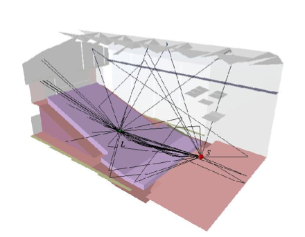
Ray-based modeling
In geometrical room acoustics, sound is assumed to propagated along straight paths or rays. The goal is to model the reflection paths from the sound source (S) to the listener (L). The paths may include multiple reflections from the surfaces of the room.

Bi-directional reflectance distribution function
The bi-directional reflectance distribution function (BRDF) determines the distribution of the outgoing acoustic radiance for an acoustic irradiance coming from a given angle. BRDFs are 4-dimensional functions with two dimensions for both incoming and outgoing angles.
Research on Geometrical Acoustics at Aalto
We have contributed to the research on geometrical acoustics by developing a theoretical framework that covers all the geometrical algorithms as special cases [7]. This has also lead to the invention of a new geometrical algorithm, namely the acoustic radiance transfer method [7]. This algorithm has been shown to accurately predict room acoustical parameters. In addition, it can be used even in interactive applications [13]. We have also introduced optimizations to the well-known beam tracing algorithm [5]. With simple models, real-time performance is achived for early reflection modeling.
The Room Acoustic Rendering Equation
We have derived a theory for geometrical room acoustics that covers all the previously mentioned modeling methods as special cases. It relates the outgoing acoustic radiance from any point on the surface of the room to other surface points. This is expressed as a surface integral. The name room acoustic rendering equation comes from its time-independent counterpart in computer graphics. [7]
Acoustic Radiance Transfer Method
We have proposed a novel room acoustics modeling method based on the room acoustic rendering equation. It is a radiance exchange method that uses directionally dependent reflection models. They are represented as bi-directional reflectance distribution functions (BRDFs), which relates the incoming acoustic irradiance to the outgoing acoustic radiance for each incoming and outgoing angle.
The modeling algorithm is called the acoustic radiance transfer (ART) method. The surface of the room is divided into elements and for each of those, the hemisphere above it is further split into directional slots. In the ART method, the acoustic radiance is propagated iteratively from element to element and from directional slot to directional slot, until the propagated energy is neglible. The initialization and final gathering phases are as desribed above in the case of radiance exchange methods in general.
The ART method produces results that are similar to the measured ones when compared with the standard room acoustical parameters. It provides flexibility in modeling different scattering materials through the use of BRDFs. [7]
Accelerated Beam Tracing
When a beam tracer is used as a part of an interactive application, where the reflection paths are calculated for a moving listener, there is coherence between the reflection paths of adjacent listener positions. This coherence can be utilized in the path calculation algorithm.
We have developed a beam tracing algorithm that does not do occlusion tests during the beam tree construction, but postpones the testing as long as possible [5]. It also does not store the clipped polygons, but only references to the original polygons, in the beam tree. This way the beam tree remains simple and it can be fairly deep. The occlusion testing is done during the path construction phase and even then it can be skipped in most cases.
The main idea is to store so-called "fail planes" for each beam. A fail plane is a plane in the hierarchical beam tree against which the path construction has previously failed. This plane is propagated to the lower levels of the beam tree by reflecting it around the surfaces like the beams. Thus, because the path is first tested against the fail plane, the path validation can be quickly terminated already at the lower levels of the beam tree in the case of an invalid paths. Because most paths tend to be invalid, this optimization can tremendeously speed up the calculation. [5]
Another optimization we have proposed for the beam tracing algorithm is the use of a "skip sphere". The beam tree nodes are grouped into "buckets" containing a few nodes. If all of them produce invalid paths, then a skip sphere is calculated around the listener and while the listener stays side that sphere all the nodes in the bucket can be skipped. The radius of the skip sphere is the minimum distance from the listner to the fail planes of the nodes in the bucket. [5]
With these optimizations, the beam tracer algorithm is acapable of updating the early reflection paths at interactive rates for a moving listener in fairly complex models.
References
[1] Krokstad, A., Strom, S., and Sørsdal, S., "Calculating the acoustical room response by the use of a ray tracing technique," Journal of Sound and Vibration, vol. 8, nr. 1, pp. 108-114, 1968.
[2] Allen, J. B. and Berkley, D. A., "Image method for efficiently simulating small-room acoustics," Journal of the Acoustical Society of America, vol. 65, nr. 4, pp. 943-950, 1979.
[3] Borish, J., "Extension of the image model to arbitrary polyhedra," Journal of the Acoustical Society of America, vol. 75, nr. 6, pp. 1827-1836, 1984.
[4] Funkhouser, T. A., Carlbom, I., Elko, G., Pingali, G., Sondhi, M., and West, J., "A beam tracing approach to acoustic modeling for interactive virtual environments," in Proceeding of the 25th Annual Conference on Computer Graphics and Interactive Techniques (SIGGRAPH '98), pp. 21-32, 1998.
[5] Laine, S., Siltanen, S., Lokki, T., Savioja, L., "Accelerated beam tracing algorithm," Applied Acoustics, vol. 70, nr. 1, pp. 172-181, 2009.
[6] Lewers, T., "A combined beam tracing and radiant exchange computer model of room acoustics," Applied Acoustics, vol. 38, nr. 2-4, pp. 161-178, 1993.
[7] Siltanen, S., Lokki, T., Kiminki, S., and Savioja, L., "The room acoustic rendering equation," Journal of the Acoustical Society of America, vol. 122, nr. 3, pp. 1624-1635, 2007.
[8] Biot, M. A. and Tolstoy, I., "Formulation of wave propagation in infinite media by normal coordinates with an application to diffraction," Journal of the Acoustical Society of America, vol. 29, nr. 3, 381-391, 1957.
[9] Medwin, H., Childs, E., and Jebsen, G. M., "Impulse studies of double diffraction: A discrete Huygen's interpretation," Journal of the Acoustical Society of America, vol. 72, nr. 3, pp. 1005-1013, 1982.
[10] Svensson, U. P., Fred, R. I., and Vanderkooy, J., "Analytic secondary source model of edge diffraction impulse responses," Journal of the Acoustical Society of America, vol. 106, nr. 5, pp. 2331-2344, 1999.
[11] Svensson, U. P. and Calamia, P. T., "Edge-diffraction impulse responses near specular-zone and shadow-zone boundaries," Acta Acustica united with Acustica, vol. 92, nr. 4, pp. 501-512, 2006.
[12] Kouyoumjian, R. G. and Pathak, P. H., "A uniform theory of diffraction for an edge in a perfectly conducting surface," Proceedings of the IEEE, vol. 62, nr. 11, pp. 1448-1461, 1974.
[13] Siltanen, S., Lokki, T., and Savioja, L., "Frequency domain radiance transfer for real-time auralization," Acta Acustica united with Acustica, vol. 95, nr. 1, pp. 106-117, 2009.